- 您现在的位置:买卖IC网 > Sheet目录1236 > PI2127-EVAL1 (Vicor Corporation)EVAL BRD FOR PI2127 60V/12A
�� �
�
�?�
�V� S� ?� PGMin� :� Controller� minimum� clamp� voltage,� 11V�
�I� VC� max� :� Controller� maximum� bias� current,� use�
�R� LIMIT� =�
�V� Z� _� MIN� ?� V� BE� (� on� )�
�I� VC� _� MAX�
�V� S� min� ?� V� S� ?� PGMax� 40� V� ?� 12� .� 5� V�
�IC� max� +� 0� .� 1� mA�
�R� PG� =� =� =� 13� .� 1� k� Ω�
�(� 50� V� ?� 11� V� )� 2� =� 116� mW�
�(� V� S� ?� max� ?� V� S� ?� PGMin� )� 2�
�PdR� PG� =� =�
�R� Z� =�
�2.0mA�
�0� .� 1� mA� :� 0.1mA� is� added� for� margin�
�Example:� 40V� <V� S-PG� <50V�
�2� .� 1� mA�
�R� PG� 13� .� 1� k� Ω�
�Alternative� Bias� Circuit� with� Device� Enable:�
�Constant� current� circuit�
�In� a� wide� operating� input� voltage� range� the� size� of� R� PG�
�may� be� become� large� to� support� power� dissipation.� A�
�simple� constant� current� circuit� can� be� used� instead� of�
�R� PG� to� reduce� power� dissipation� and� can� be� used� as� a�
�device� enable.�
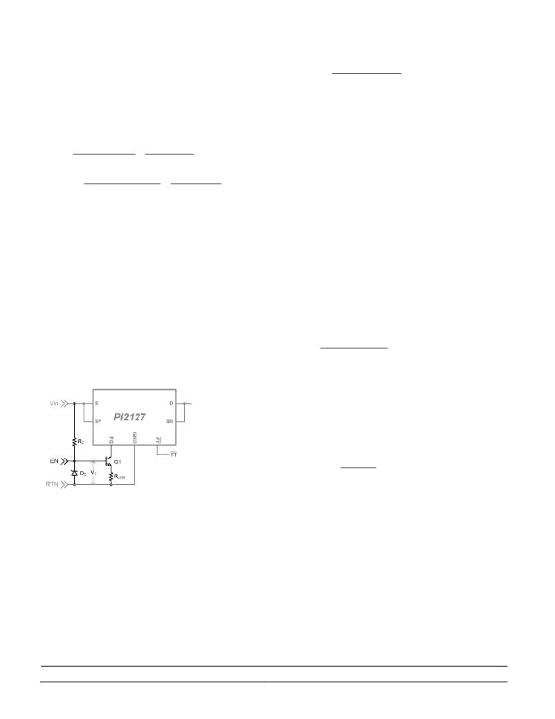
�As� shown� in� Figure� 20,� the� constant� current� circuit�
�consists� of� an� NPN� transistor� (Q1),� Zener� diode� D� Z� ,�
�current� limit� resistor� (R� LIMIT� )� and� Zener� bias� resistor�
�(R� Z� ).� R� LIMIT� and� R� Z� can� be� very� low� power� resistors�
�and� Q1� is� a� signal� transistor� where� its� Collector-�
�Emitter� Voltage� (V� CEO� )� is� equal� or� greater� than� the�
�input� operating� voltage� and� supports� 2.5mA� at� the�
�operating� input� voltage.�
�Where:�
�V� Z� _� MIN� :� Minimum� Zener� diode� voltage�
�V� BE� (� on� )� :� Q1� Base-Emitter� On� maximum� voltage,� for�
�default� use� V� BE� (� on� )� =0.7V�
�Zener� Diode� Selection:�
�Select� a� Zener� diode� with� a� low� reverse� current�
�requirement� to� minimize� R� Z� .� Zener� diodes� with� higher�
�break� down� voltage� will� have� lower� reverse� current�
�and� reduce� Q1� collector� current� variation.� Zener�
�diodes� with� a� breakdown� voltage� of� 6V� and� higher� will�
�require� low� bias� current� for� accurate� voltage�
�breakdown.�
�R� Z� maximum� value� can� be� calculated� with� the�
�following� equation:�
�Note� that� the� surface� mount� resistors� have� limited�
�operating� voltage� capability.� Be� sure� to� pick� a� resistor�
�package� that� can� meet� the� maximum� operating�
�voltage� (Vin).�
�V� in� _� MIN� ?� V� Z� _� MAX�
�I� Z� +� I� B� _� MAX�
�Where:�
�V� in� _� MIN� :� Min� input� voltage�
�V� Z� _� MAX� :� Zener� diode� maximum� breakdown� voltage�
�I� Z� :� Zener� diode� required� reverse� current�
�I� B� _� MAX� :� Q1� required� maximum� base� current� which�
�calculated� from� the� following� equation:�
�I� B� _� MAX� =�
�I� C� _� MAX�
�h� FE� _� MIN�
�Figure� 20:� Constant� current� bias� circuit�
�Pulling� the� Q1� base� (EN)� to� the� system� return� (RTN)�
�will� turn� off� the� transistor� and� the� controller� return� (PG�
�pin)� will� float� and� eventually� the� MOSFET� will� be�
�turned� off.� An� open� collector� device� can� be� used� to�
�enable� and� disable� the� PI2127.�
�The� constant� current� circuit� should� guarantee� current�
�greater� than� the� PI2127� maximum� Quiescent� current�
�(I� VC� ),� 2.0mA.�
�R� LIMIT� can� be� calculated� from� the� following� equation:�
�I� C� _� MAX� :� Q1� maximum� expected� collector� current.�
�h� FE� _� MIN� :� Q1� minimum� gain.�
�Internal� N-Channel� MOSFET� BV� DSS� :�
�The� PI2127’s� internal� N-Channel� MOSFET�
�breakdown� voltage� (BV� DSS� )� is� rated� for� 60V� at� 25°C�
�and� will� degrade� to� 55.5V� at� -40°C,� refer� to� Figure� 10.�
�Drain� to� source� voltage� should� not� exceed� BV� DSS� in�
�nominal� operation.� During� a� fast� switching� transient�
�the� MOSFET� can� tolerate� voltages� higher� than� its�
�BV� DSS� rating� under� avalanche� conditions,� refer� to� the�
�Absolute� Maximum� Ratings� table.�
�In� Active� ORing� applications� when� one� of� the� input�
�power� sources� is� shorted,� a� large� reverse� current� is�
�Picor� Corporation� ?� picorpower.com�
�PI2127�
�Rev� 1.3�
�Page� 11� of� 19�
�发布紧急采购,3分钟左右您将得到回复。
相关PDF资料
PI2161-EVAL1
EVALUATION BOARD FOR PI2161
PI2211-EVAL1
BOARD EVAL FOR PI2211
PI5101-EVAL1
EVALUATION BOARD FOR PI5101
PICOSMDC035S-2
POLYSWITCH PTC RESET .35A 0805
PIIPM25P12B008X
IC PWR MODULE PROG ISO 25A 1200V
PK3020KB
KIT KEYPAD, MOUSE, AND USB HUB
PK3021LI
KIT LIGHT, MOUSE, AND USB HUB
PK3022ET
KIT CAT5 CABLE MOUSE USB HUB
相关代理商/技术参数
PI2140DG-22H
制造商:PDI 制造商全称:PDI 功能描述:HIGH POWER DROP-IN ISOL
PI214MC-DR
制造商:AMI 制造商全称:AMI 功能描述:200DPI CIS Two Level Digital Output Module
PI214MC-DR-BVGL
制造商:ON Semiconductor 功能描述:IMAGE SENSOR - Bulk
PI21-5,08
功能描述:可插拔接线端子 PCB Hdr, 45 Deg, 5,08 PitchOpen End, 21pole, 12A,300V,Grn RoHS:否 制造商:Phoenix Contact 产品:Plugs 系列:PTS 端接类型:Spring Cage 位置/触点数量:5 线规量程:26-14 节距:5 mm 电流额定值:10 A 电压额定值:250 V 安装风格: 安装角: 触点电镀:
PI2161-01-LGIZ
功能描述:60V 12A FULL-FUNCTION LOAD 17LGA RoHS:是 类别:集成电路 (IC) >> PMIC - MOSFET,电桥驱动器 - 内部开关 系列:Picor®, Cool-Switch® 其它有关文件:VND5E050AK-E View All Specifications 产品培训模块:VIPower™ M0-5 Smart Power Devices 标准包装:1,000 系列:VIPower™ 类型:高端 输入类型:非反相 输出数:2 导通状态电阻:50 毫欧 电流 - 输出 / 通道:19A 电流 - 峰值输出:27A 电源电压:4.5 V ~ 28 V 工作温度:-40°C ~ 150°C 安装类型:表面贴装 封装/外壳:24-SOP(0.295",7.50mm 宽)裸露焊盘 供应商设备封装:PowerSSO-24 包装:带卷 (TR) 其它名称:497-11699-2VND5E050AKTR-E-ND
PI2161-EVAL1
功能描述:EVALUATION BOARD FOR PI2161 RoHS:是 类别:编程器,开发系统 >> 评估演示板和套件 系列:Picor®, Cool-Switch® 标准包装:1 系列:- 主要目的:数字电位器 嵌入式:- 已用 IC / 零件:AD5258 主要属性:- 次要属性:- 已供物品:板 相关产品:AD5258BRMZ1-ND - IC POT DGTL I2C1K 64P 10MSOPAD5258BRMZ10-ND - IC POT DGTL I2C 10K 64P 10MSOPAD5258BRMZ100-ND - IC POT DGTL I2C 100K 64P 10MSOPAD5258BRMZ50-ND - IC POT DGTL I2C 50K 64P 10MSOPAD5258BRMZ1-R7-ND - IC POT DGTL I2C 1K 64P 10MSOPAD5258BRMZ10-R7-ND - IC POT DGTL I2C 10K 64P 10MSOPAD5258BRMZ50-R7-ND - IC POT DGTL I2C 50K 64P 10MSOPAD5258BRMZ100-R7-ND - IC POT DGTL I2C 100K 64P 10MSOP
PI216MC-DR
制造商:AMI 制造商全称:AMI 功能描述:200DPI CIS Two Level Digital Output Module
PI2211-00-QAIG
功能描述:IC HOT SWAP CONTROLLER 24QFN RoHS:是 类别:集成电路 (IC) >> PMIC - 热交换 系列:Picor®, Cool-Swap™ 标准包装:50 系列:- 类型:热交换控制器 应用:-48V 远程电力系统,AdvancedTCA ? 系统,高可用性 内部开关:无 电流限制:可调 电源电压:11.5 V ~ 14.5 V 工作温度:-40°C ~ 85°C 安装类型:表面贴装 封装/外壳:10-TFSOP,10-MSOP(0.118",3.00mm 宽) 供应商设备封装:10-MSOP 包装:管件